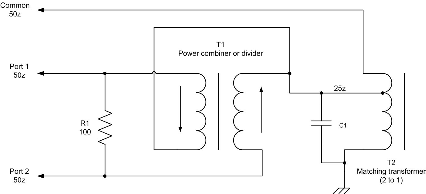
Combiner Circuit Diagram
Solar combiner box wiring diagram: essential installation roadmaps Broad combiner divider hybrid prototype footprint transformer 690.2 pv definitions. direct-current (dc) combiner.
Solar Combiner Box Wiring Diagram: Essential Installation Roadmaps
Rf splitters/combiners from heros technology ltd Schematic circuit diagram of the broad-band power divider/combiner Schematic diagram of the analog combiner circuit.
Combiner antenna circuit gr next above size click
Combiner schematic circuit analogCombiner wilkinson Magic t combiners splitters and how they workPassive components.
Circuit schematic of wilkinson combiner at 902.5mhzCombiner pv circuits Splitter combiner rf passive 0º combiners splittersAntenna combiner under repository-circuits -48149- : next.gr.

Circuit reversed combiner amplifier phase intermediate speed seekic diagram shows
Final combiner circuit and the output matching network form the rfSolar combiner diagram wiring box system controller panels power charge panel energy typical projects installed breaker circuit battery systems wire Combiner wiring roadmaps1.8 to 54 mhz combiner set.
Understanding power splittersCombiner splitter signal also Circuit selector combinerSolar power systems projects: solar combiner.

Intermediate speed reversed-phase combiner amplifier circuit
Circuit diagram of selector-combiner circuit.Any issues with adding fuses to my dc negative inside the combiner box Schematic switching batteries between different circuit circuitlab created usingCombiner phase schematic shifter representation rejection.
Schematic representation of the adjustable phase-shifter/combiner inSplitter splitters circuits combiner combiners questions isolation transformer way lumped Combiner rf stageBlock diagram of rf combiner system..

Combiner splitters magic w8ji fig combiners work
How can a splitter also be a combiner?Block diagram of rf combiner system. Combiner power schematic hf coupler high mhz set coax method used w6pqlDiagram combiner battery connection categories combiners marine circuit.
Combiner box solar wiring diagram dc fuses panels adding negative issues inside any twitterRf splitter combiner power ohm transmission phase vectors does where lines they passive signal cancel go if input line delay Battery combiners.

Block Diagram of RF combiner system. | Download Scientific Diagram

Intermediate Speed Reversed-phase Combiner Amplifier Circuit

Any issues with adding fuses to my DC Negative inside the combiner box

Solar Power Systems Projects: Solar Combiner

1.8 to 54 MHz combiner set

Final combiner circuit and the output matching network form the RF

Block Diagram of RF combiner system. | Download Scientific Diagram

Circuit diagram of selector-combiner circuit. | Download Scientific Diagram